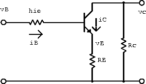
The CE amplifier is often constructed with an emitter resistor ![]() as shown in figure 5.9.
This resistor provides a form of negative feedback that can be used to
stabilize both the DC operating point and the AC gain.
It can be shown that the voltage transfer function across the
transistor is
as shown in figure 5.9.
This resistor provides a form of negative feedback that can be used to
stabilize both the DC operating point and the AC gain.
It can be shown that the voltage transfer function across the
transistor is
![]()

Figure 5.9: CE amplifier with emitter resistor.
If ![]() , the gain becomes independent of the hybrid
parameters:
, the gain becomes independent of the hybrid
parameters:
![]()
Because it is unaffected by variations in the hybrid parameters, this result is valid even for a large-amplitude signal.
The input resistance can be shown to be ![]() .
Since
.
Since ![]() is small, it can usually be neglected whenever the
emitter impedance is more than a few hundred ohms.
is small, it can usually be neglected whenever the
emitter impedance is more than a few hundred ohms.
For small input signals it is often desirable to retain the large
voltage gain of the basic CE amplifier even though an emitter resistor
is used for DC stability.
This can be done if a large capacitor ![]() is used to bypass the AC
signal around the emitter resistor.
is used to bypass the AC
signal around the emitter resistor.
![]() shorts out the emitter bias resistor
shorts out the emitter bias resistor ![]() for AC signals.
The magnitude of the resulting transfer function is similar to a
high-pass filter, with
for AC signals.
The magnitude of the resulting transfer function is similar to a
high-pass filter, with ![]() setting the gain (
setting the gain ( ![]() ) at low
frequencies and the capacitor maximizing the gain
(
) at low
frequencies and the capacitor maximizing the gain
( ![]() ) at high frequencies.
) at high frequencies.
Example: Determine values forand
that will yield the operating point shown in the circuit in figure 5.10 (
) under the assumption that:
.

.
Therefore


V.
.
.
Therefore


- Repeat both calculations for
.
For
,
remains unchanged.
.
.

Figure 5.10: Example transistor circuit with a single bias transistor.
Example:
- If
, determine an expression for the base-biasing resistor
that will result in a DC operating point
for the circuit in figure 5.11.
Now
. The voltage drop across the bias resistor is
. Charge conservation
gives
The voltage at the base is
. Neglecting the
voltage drop gives

EliminOAating
gives
. Using
gives
Substituting equation 5.35 into equation 5.33 gives
The voltage drop across the collector resistor is

Therefore

- If the circuit is built with the
just found, what will be the operating point if
?
If
and
,
.
Substitution into equation 5.36 gives


Figure 5.11: Example transistor circuit with two bias resistors.