inverts the state of an output pin.
In assembly language, inverting the state of a pin (or any bit, for that matter) is a matter of XORing the register with a value containing a 1 in the corresponding position. For example, to invert bit 2 of port RA, you would use the instructions XOR ra, #00000100b.
PBASIC's Toggle also changes the pin's data direction to output by putting a 0 in the appropriate bit of the tristate (TRIS) register. (In assembly, a 0 in TRIS means makes a pin and output; a 1 makes it an input. This is the opposite of the BASIC Stamp.) The assembly-language example here changes only the output latch, not TRIS.
Of course, if you use a literal number to toggle a pin's state with XOR, you cannot change the pin to be toggled while the program is running. The literal number is coded as part of the machine-language instruction. The accompanying program listing is a port- and pin-independent Toggle routine. Write the pin number to pin, the port number to w, and call Toggle.
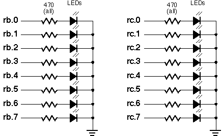
To see Toggle in operation, either run the program with the PSIM simulator, or connect the circuit below to an erasable PIC or PIC emulator, such as the Parallax downloader. Assemble and run TOGGLE.SRC. When you apply power to the PIC, the LEDs connected to ports RB and RC will be inverted one-by-one, beginning with RB.0.

;
; ***************************************************************************
; ***  Bubble Software Parallax to PIC Source Converter. Copyright 1999.  ***
; ***  http://www.bubblesoftonline.com                 email: sales@picnpoke.com  ***
; ***************************************************************************
;
; TOGGLE port (in w), pin
; Toggles (inverts) the state of the specified port and pin.


; Device data and reset vector
	P = pic16c55
	#include <16c55.inc>   ; processor assembler definitions
	_CONFIG _xt_osc & _wdt_off & _protect_off
 reset start

	org 8
pin 		Res 	d'1' 	; Pin number to set (0-7).

; Variables for the demo program--not required by Toggle.
p_index 	Res 	d'1' 	; Copy of pin number, port number.
temp 		Res 	d'1' 	; Temporary variables for time delay
temp2 		Res 	d'1' 	; between outputs.

	org 0

; Table to convert pin number (0-7) into bit mask (00000001b to 10000000b).
Pinz         ADDWF pcl
             RETLW d'1'
             RETLW d'2'
             RETLW d'4'
             RETLW d'8'
             RETLW d'16'
             RETLW d'32'
             RETLW d'64'
             RETLW d'128'

; The following demonstration code should show the value of being able to
; toggle a particular bit of a port based on a calculation performed while the
; program is running. As the variable p_index is incremented from 0 to 15,
; it is used to specify the pin and port to invert using Toggle.

start        MOVLW d'0'                 ; All outputs on rb.
             TRIS 6h
             MOVLW d'0'                 ; All outputs on rc.
             TRIS 7h
             MOVLW b'10101010'          ; Put a pattern of alternating lights
             MOVWF 6h
             MOVLW b'10101010'          ; onto rb and rc.
             MOVWF 7h
             CLRF p_index               ; Clear p_index.
start_loop   MOVLW d'7'                 ; Copy three lsbs of p_index into
             MOVWF pin
             MOVF p_index               ; variable pin.
             ANDWF pin
             MOVLW d'1'                 ; IF p_index.3 = 0

             BTFSC p_index,d'3'         ; THEN w = 1
             MOVLW d'2'                 ; ELSE w = 2
             CALL Toggle
             CALL delay                 ; Wait a while between toggles.
             INCF p_index               ; Next pin/port.
             BTFSS p_index,d'4'         ; IF p_index < 15 (rc.7)
             GOTO start_loop            ; THEN :loop ELSE done
done         GOTO $                     ; Endless loop.

; To use the routine Toggle, put the pin number into the variable pin
; and the port number into w. Then call Toggle.

Toggle       MOVWF fsr                  ; Point to the port number.
             MOVLW 5h                   ; Add offset for port RA.
             ADDWF fsr
             MOVF pin,w
             CALL Pinz                  ; Get bit mask from the table.
             XORWF indirect             ; Invert the selected bit
             RETLW 0h

; Delay routine for demonstration. Not required by Toggle.

delay        DECFSZ temp                ; Time delay to provide spacing
             GOTO delay
             DECFSZ temp2               ; between highs.
             GOTO delay
             RETLW 0h

             end


; TOGGLE port (in w), pin
; Toggles (inverts) the state of the specified port and pin.

	org	8
pin	ds	1	; Pin number to set (0-7).

; Variables for the demo program--not required by Toggle.
p_index	ds	1	; Copy of pin number, port number.
temp	ds	1	; Temporary variables for time delay
temp2	ds	1	; between outputs.

; Device data and reset vector
	device	pic16c55,xt_osc,wdt_off,protect_off
	reset	start
	org	0

; Table to convert pin number (0-7) into bit mask (00000001b to 10000000b).
Pinz	jmp	pc+w
	retw	1,2,4,8,16,32,64,128

; The following demonstration code should show the value of being able to
; toggle a particular bit of a port based on a calculation performed while the
; program is running. As the variable p_index is incremented from 0 to 15,
; it is used to specify the pin and port to invert using Toggle.

start	mov	!rb, #0 ; All outputs on rb.
	mov	!rc, #0 ; All outputs on rc.
	mov	rb,#10101010b	; Put a pattern of alternating lights
	mov	rc,#10101010b	; onto rb and rc.
	clr	p_index ; Clear p_index.
:loop	mov	pin,#7	; Copy three lsbs of p_index into
	AND	pin,p_index	; variable pin.
	mov	w,#1	; IF p_index.3 = 0

	snb	p_index.3	; THEN w = 1
	mov	w,#2	; ELSE w = 2
	call	Toggle
	call	delay	; Wait a while between toggles.
	inc	p_index ; Next pin/port.
	sb	p_index.4	; IF p_index < 15 (rc.7)
	jmp	:loop	; THEN :loop ELSE done
done	jmp	$	; Endless loop.

; To use the routine Toggle, put the pin number into the variable pin
; and the port number into w. Then call Toggle.

Toggle	mov	fsr,w	; Point to the port number.
	ADD	fsr,#RA ; Add offset for port RA.
	mov	w,pin
	call	Pinz	; Get bit mask from the table.
	XOR	indirect,w	; Invert the selected bit
	ret

; Delay routine for demonstration. Not required by Toggle.

delay	djnz	temp,delay	; Time delay to provide spacing
	djnz	temp2,delay	; between highs.
	ret
See also:
Code: