Fr. Thomas McGahee says
The TEAC Floppy typically uses a 5 wire stepper motor. One of the wires is a COMMON which is tied to one side of each of the four unipolar coils. You can easily determine which wire is the COMMON by using an ohmmeter. There will be only one wire that will measure the same value with respect to all the other four wires.Connect the COMMON to +12v. Arbitrarily label one of the wires "A". Connect "A" to ground. At this point the stepper motor will lock into a fixed detent position. One at a time short each of the other wires to ground. You will find that one wire makes the shaft move clockwise a small amount, and one wire makes the shaft move counter- clockwise by the SAME amount. Label the wire that caused the shaft to rotate CW "B". Label the wire that made the shaft rotate CCW "D". Label the remaining wire "C".
The stepper motor will rotate full-step CW if the sequence is thus: A B C D A B C D A B C D etc.
The stepper motor will rotate full-step CCW if the sequence is thus: A D C B A D C B A D C B etc.
The stepper motor will rotate half-step CW if the sequence is thus: A AB B BC C CD D DA A AB B BC C CD D DA etc.
The stepper motor will rotate half-step CCW if the sequence is thus: A AD D DC C CB B BA A AD D DC C CB B BA etc.
A diode should be connected across each coil winding. The Anodes all connect to the Common wire, and the Cathodes connect to A B C and D.
The diode will supress high voltage spikes when the coil is switched from it's ON to it's OFF state.
You can drive the windings to ground via a grounded HexFet, or even a decent bipolar transistor such as a Motorola MPS6566. The transistor must be capable of handling the current through the winding, which can be computed using Ohm's Law: I=E/R where R is the DC resistance of the coil.
The transistor or HexFet is used as a switch. When it is OFF the voltage across it is +12v and the current is zero. When it is fully ON, the current will be from a few hundred milliamps to perhaps an amp or so (depending on the stepper motor), and the voltage across the switching device will be only a few tenths of a volt. In either case the POWER dissipation of the device can be kept quite low so long as the switching device is driven *hard*.
The maximum speed at which the typical floppy stepper motor can be stepped is between 200 and 300 steps per second. As the speed increases, torque will decrease until finally the motor becomes erratic and loses synch.
It is possible to increase the speed significantly by using a chopper mode with feedback which keeps the ON current constant. In this case the compliance voltage is raised to over 24 volts. However, such techniques are normally reserved for driving large high power stepper motors. It would be over-kill to do this with a floppy stepper motor.
As to driving the stepper motor via a PIC, it is ridiculously easy. You assign four I/O pins to drive the ABCD driver transistors. If using full-step mode, you can simply shift 2 bits left or right in a register and then copy the least significant 4 bits to the I/O pins. Initial "seed" value would be binary 00010001. Just make sure that when you shift the carry value is properly set up based whether you are shifting left or right.
I have to go right now, but if anyone has any further questions, ask away. As usual, this is only ONE of MANY POSSIBLE ways to do things. If you have a preferred method of doing this, share it with the rest of us.
jb [alphaone at ROF.NET] says:
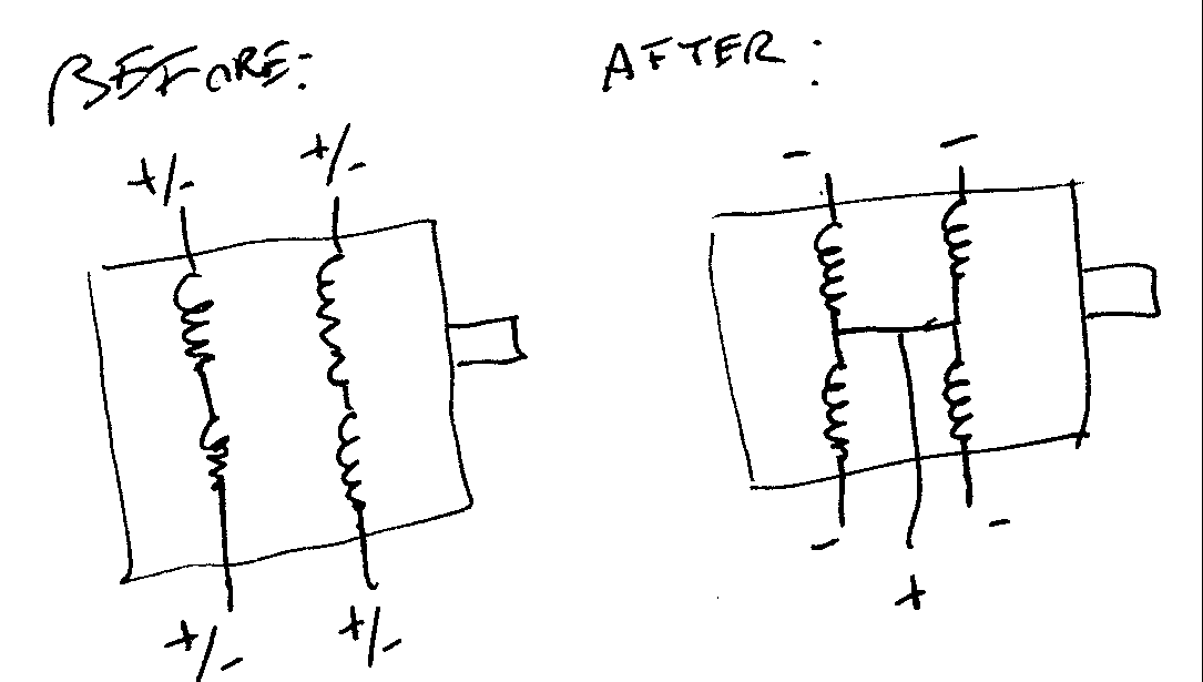
I have taken those bipolar floppy steppers apart and tapped the wire that connects the two coils on either side. In other words, there are four coils internally, two sets of two. Each coil in a set is connected, usually by the same enamel wire that the coil in comprised of. If you tap this connection on each set, tie them together, then run out a fifth wire from that junction, you now have a unipolar stepper rated at half the voltage (6V in your case) and twice the current. You then need only figure out the step sequence.

Questions:
| file: /Techref/io/stepper/floppy.htm, 6KB, , updated: 2006/6/16 09:13, local time: 2025/4/25 08:33,
3.15.22.202:LOG IN
|
| ©2025 These pages are served without commercial sponsorship. (No popup ads, etc...).Bandwidth abuse increases hosting cost forcing sponsorship or shutdown. This server aggressively defends against automated copying for any reason including offline viewing, duplication, etc... Please respect this requirement and DO NOT RIP THIS SITE. Questions? <A HREF="http://linistepper.com/techref/io/stepper/floppy.htm"> io stepper floppy</A> |
| Did you find what you needed? |