+
Shows a simple photosensor circuit, and compares it to much more complicated (living) stuff.

The purpose of the photodiode is to serve as a light sensor (like Cph8 and
the phycobilins) and the LED as a readout (like lacZ). The 150Ù resistor
is there to ensure that the voltage drop across the LED isn't too high (which
can cause the LED to breakdown). The inverter provides a convenient way of
connecting the photodiode to the LED. The other resistor RL is there to ensure
that the signal between the photodiode and inverter are matched. When light
shines on the photodiode, its resistance is decreased and current flows through
it. Thus, point a in the circuit diagram is at high voltage (near +5V) and
the input signal to the inverter is high. The low output signal (point b)
from the inverter creates a voltage drop across the LED causing it to turn
on and emit light. In the absence of light, the photodiode has high resistance
such that little current flows. Point a in the diagram is at low voltage
(near 0V) and the inverter produces high output at point b. The resulting
lack of voltage drop across the LED means that the LED is turned off. Much
of this exercise will focus on RL and ensuring that the signal between the
photodiode and inverter are matched for proper circuit
operation.
VIH / IL < RL < VIL /
ID
• VIL: Highest voltage at point a that is a low input signal
for the inverter.
• VIH: Lowest voltage at point a that is a high input signal
for the inverter.
• IL: Current that flows through the photodiode when light
is shone on it.
• ID: Current that flows through the photodiode when it is
in the dark.

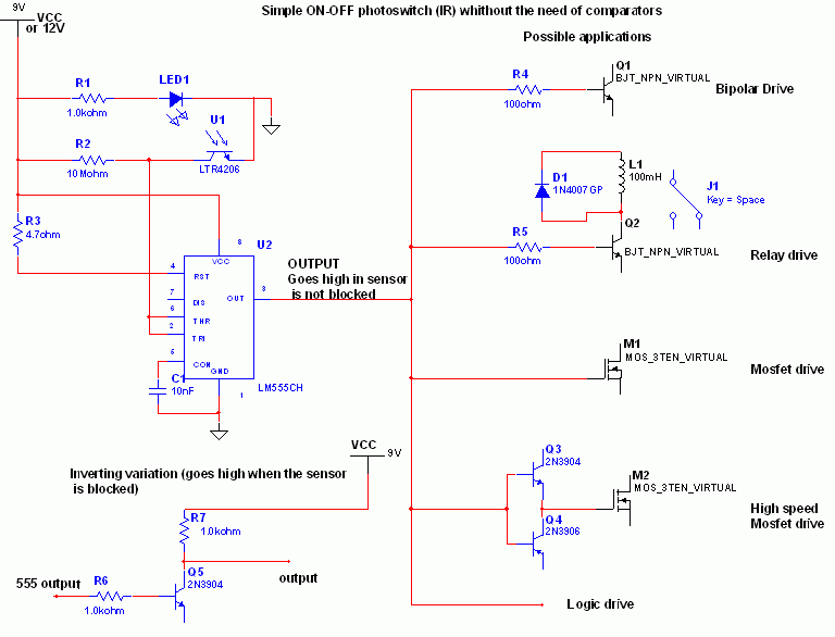
When the phototransistor is struck by IR light it conducts and the voltage between the 1Mohm resistor(arbitrary) and the phototrans drops from VCC to lower values. When the voltage drops lower than VCC/3 the 555 is triggered and goes high (from 0 TO VCC). The amount of light that strike the phototrans necessary to bring his collector to VCC/3 is determined by the resistor (Vdrop = Icollector * R , so , if Vdrop= 2*VCC/3, the resistance needed to set the threshold on current is R=2*VCC/(Icollector*3)). High sensitivity phototrans would need a smaller resistor, and weaker phototransistors higher value resistor, you can also use a trimmer to set the "on" threshold level with precision. The type of phototransistor isn't critical. The 555 has high current capability and can drive various devices, such as Bipolars, relays, bipolars+relays, mosfets, mosfets + totem pole , or give a logic output (see pic).
In case you need to trigger something when the gate is blocked (for example a burglar alarm, or a multistage coilgun) you need to invert the output, which is accomplished using a small bipolar transistor wired in an inverting setup (see pic) or by swapping the positions of phototransistor with the resistor, so the voltage will drop under VCC/3 when blocked: The formula to determine the resistance to turn off at Icollector is R=VCC/(Icollector*3).