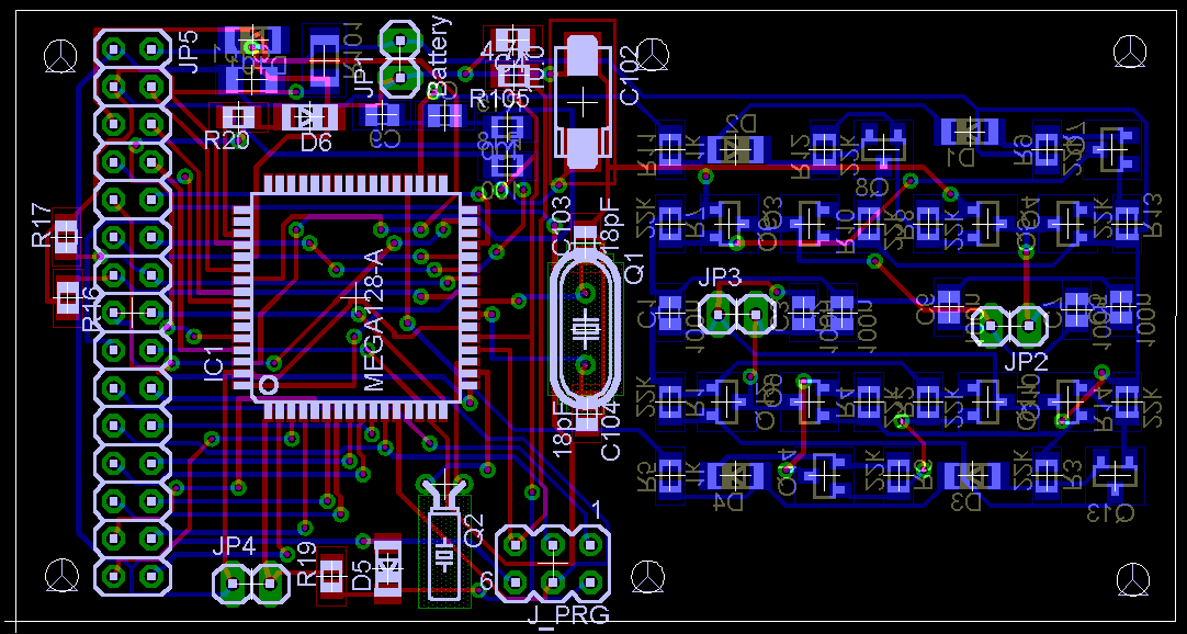
A small robot board with the
AVR
by Dimitar Dimitrov
 This is a quick test for the
AVRbot board. Briefly, you navigate the robot via q,a,z,w,s,x keys, sent
through RS-232 interface.
q - turn left motor forward
a - turn off left motor
z - turn left motor backward
w - turn right motor forward
s - turn off right motor
x - turn right motor backward
The provided hex file is for a 11.0592 MHz crystal and 115200 RS-232
communication . Please take a look at main.h and main.c and adjust it to
your needs. Then recompile with avr-gcc. Note that this is built as a development
board. You access most of the controller's peripherals through header JP5.
It's up to you if you want to improve the system. Or you can wait until I
finish mine as I will publish both schematics for sensors and software for
handling them.
You must provide a TTL (0-5V) level to the AtMega128 serial channel. Connect
to RXD and TXD. Some new PC mother boards automatically detect 5V and in
this case you won't need MAX232 to convert levels. Be aware that if your
mother board doesn't support this detection you will blow the controller.
You have been warned.
If you have questions, read the source code. If still in trouble you can
write to dinux at mail dot bg.
+
Board and schematic +
main.c +
main.h +
motors.c +
motors.h +
Interested:
| file: /Techref/atmel/avr/avrbot.htm, 2KB, , updated: 2013/7/22 17:16, local time: 2025/4/25 15:17,
owner: JMN-EFP-786,
|
| | ©2025 These pages are served without commercial sponsorship. (No popup ads, etc...).Bandwidth abuse increases hosting cost forcing sponsorship or shutdown. This server aggressively defends against automated copying for any reason including offline viewing, duplication, etc... Please respect this requirement and DO NOT RIP THIS SITE. Questions?
<A HREF="http://linistepper.com/techref/atmel/avr/avrbot.htm"> A small robot board with the AVR</A> |
| Did you find what you needed?
|
 This is a quick test for the
AVRbot board. Briefly, you navigate the robot via q,a,z,w,s,x keys, sent
through RS-232 interface.