
PIC DOGM ST7036
LCD
by Jinx
DOGM are a COG (chip on glass) style of LCD which is an attractive
alternative to the standard alphanumeric display. The space behind
the display and its transparency, as well as the functionality of the
controller, make options available to the user not possible with self-
contained modules
This page is here to demonstrate initialisation with a PIC, as much of
the material out there purporting to do this is confused, misleading
or just wrong
Manufacturer's site
http://www.lcd-module.com/products/dog.html
At this time, April 2011, DOGM LCDs are in stock at Mouser

Unlit, daylight

lit, diffused white LEDs
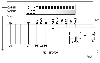 Tested on PIC 18F2520, 39.3216MHz (9.8304MHz PLL)
LCD Vdd = 5V, 8-bit parallel mode
;macros
line1 macro
movlw 0x00+0x80 ;line 1, column 0
call writec
endm
line2 macro
movlw 0x40+0x80 ;line 2, column 0
call writec
endm
display macro var ;load TBLPTR with string address
movlw upper(var)
movwf tblptru
movlw high(var)
movwf tblptrh
movlw low(var)
movwf tblptrl
tblrd*+
call get_txt ;get characters, print
endm
;PortC 0-7 - LCD data
#define rs latb,1 ;RS
#define rw latb,2 ;R/W
#define en latb,3 ;Enable
;example definitions
function1 = 0x39
function2 = 0x38
bias = 0x1c
power = 0x52
follower = 0x69
contrast = 0x74
disp_on = 0x0c
disp_off = 0x08
clear = 0x01
entry = 0x06
crsr_on = 0x0f
crsr_off = 0x0c
ddram = 0x80
cgram = 0x40
strings = 0x400 ;display string storage address
bcf en
bcf rw
bcf rs
call ms100 ;> 18ms delay
call lcd_init
display m1 ;show Line1 text
line2
display m2 ;show Line2 text
;================================================
; Initialise LCD screen (8-bit, 5V)
;================================================
;The 162 initialisation sequence found on page 7 of
;Electronic Assembly's product guide
;
;http://www.lcd-module.de/eng/pdf/doma/dog-me.pdf
http://www.lcd-module.de/eng/pdf/doma/dog-me.pdf
;is substantially correct, although it doesn't contain
;other required information found in the ST7036 datasheet
;
;The initialisation sequences and code examples in
;the ST7036 datasheet, however, are just plain rubbish
;
;(IMVHO)
;
;You should have it though
;
;http://www.lcd-module.com/eng/pdf/zubehoer/st7036.pdf
http://www.lcd-module.com/eng/pdf/zubehoer/st7036.pdf
lcd_init movlw function1 ;must use this sequence
call writec
movlw power
call writec
movlw contrast
call writec
movlw bias
call writec
movlw follower
call writec
movlw function2
call writec
movlw disp_on
call writec
movlw clear
call writec
call ms01
call ms01
movlw entry
call writec
return
;================================================
writec bcf rs
bcf rw
bsf en
movwf d_temp ;temp if W over-written by delay
call us100 ;> 96us delay
movfw d_temp
movwf latc
bcf en
call us100 ;> 78us delay
return
writed bsf rs
bcf rw
bsf en
movwf latc
bcf en
call us30 ;> 15us delay
return
;================================================
; Fetch string for LCD
;================================================
; LCD text strings
get_txt movfw tablat ;get characters until
btfsc wreg,7 ;W > 0x7f (ie FF terminator)
return
call writed ;print W
tblrd*+
bra get_txt
;================================================
; LCD text strings
;================================================
org strings
m1 db "Gettin' it done",0xff
m2 db "WWW.PICLIST.COM",0xff
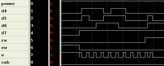
In this analyser shot of the initialisation sequence, note that Busy (D7)
is useless
for interrogation. As soon as R/W goes low, Busy goes high, and remains
there.
writec has two 100us delays that must be done. The completion time for
writed
is quite short, around 20us, so a wait delay would probably be practical
for most
software. If not, the user will have to make sure enough time has elapsed
before
attempting to write more data
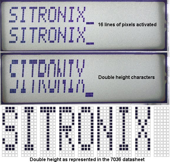
So far I've not been able to get a double-height display that looks like
the one
in the datasheet. As far as I can tell, there is no central line of pixels
to fill the
gap. All 16 rows are accounted for. If this is true, double height would
be of
limited use. joecolquitt@clear.net.nz please if you find any missing pixels
or have
the command values to display double height as seen in the datasheet. The
double
height datasheet illustration, by the way, uses an undocumented "S" and is
not
italicised, so make of that what you will
Serving suggestions

lit, red cellophane

lit, green wine bottle

lit, printed paper insert (transparency would be much better)
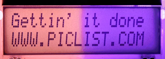
lit, pink/purple cellophane
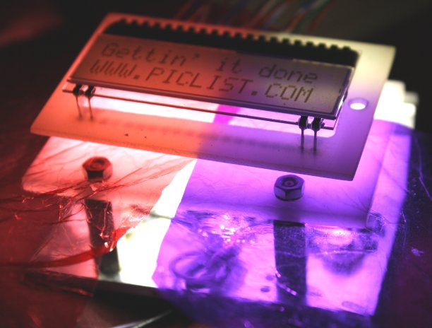
backlight jig, using dimmable 3 x 1W white LEDs and opalescent acrylic
PCB
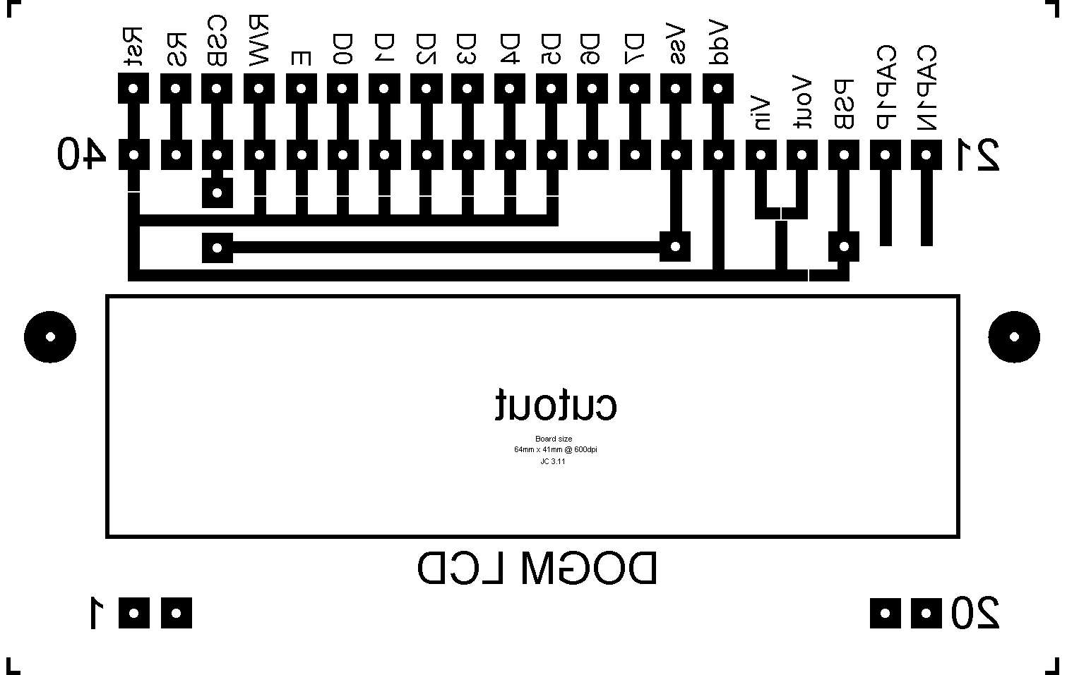
This PCB can be wired to suit any of the 6 options in the dog-me.pdf. It's
the
pattern I've used for toner transfer. Make sure that the solder bridge gaps
are
open after etching, or amend the diagram to suit your hard-wired
configuration
EA have an Eagle library, ea.lbr, in their Downloads section
The cutout can be removed if you want the lighting to be further back,
which
will help the light spread and improve evenness
Note that COG displays are fragile and trying to remove one from a PCB
could
cause it to be damaged
Copied with permission from:
http://home.clear.net.nz/pages/joecolquitt/dogm_lcd.html
See also:
| file: /Techref/microchip/io/dev/lcd/DOGM.htm, 7KB, , updated: 2011/4/22 17:44, local time: 2025/4/28 04:09,
|
| | ©2025 These pages are served without commercial sponsorship. (No popup ads, etc...).Bandwidth abuse increases hosting cost forcing sponsorship or shutdown. This server aggressively defends against automated copying for any reason including offline viewing, duplication, etc... Please respect this requirement and DO NOT RIP THIS SITE. Questions?
<A HREF="http://linistepper.com/Techref/microchip/io/dev/lcd/DOGM.htm"> DOGM LCD PIC</A> |
| Did you find what you needed?
|


 Tested on PIC 18F2520, 39.3216MHz (9.8304MHz PLL)
LCD Vdd = 5V, 8-bit parallel mode
;macros
line1 macro
movlw 0x00+0x80 ;line 1, column 0
call writec
endm
line2 macro
movlw 0x40+0x80 ;line 2, column 0
call writec
endm
display macro var ;load TBLPTR with string address
movlw upper(var)
movwf tblptru
movlw high(var)
movwf tblptrh
movlw low(var)
movwf tblptrl
tblrd*+
call get_txt ;get characters, print
endm
;PortC 0-7 - LCD data
#define rs latb,1 ;RS
#define rw latb,2 ;R/W
#define en latb,3 ;Enable
;example definitions
function1 = 0x39
function2 = 0x38
bias = 0x1c
power = 0x52
follower = 0x69
contrast = 0x74
disp_on = 0x0c
disp_off = 0x08
clear = 0x01
entry = 0x06
crsr_on = 0x0f
crsr_off = 0x0c
ddram = 0x80
cgram = 0x40
strings = 0x400 ;display string storage address
bcf en
bcf rw
bcf rs
call ms100 ;> 18ms delay
call lcd_init
display m1 ;show Line1 text
line2
display m2 ;show Line2 text
;================================================
; Initialise LCD screen (8-bit, 5V)
;================================================
;The 162 initialisation sequence found on page 7 of
;Electronic Assembly's product guide
;
;http://www.lcd-module.de/eng/pdf/doma/dog-me.pdf
http://www.lcd-module.de/eng/pdf/doma/dog-me.pdf
;is substantially correct, although it doesn't contain
;other required information found in the ST7036 datasheet
;
;The initialisation sequences and code examples in
;the ST7036 datasheet, however, are just plain rubbish
;
;(IMVHO)
;
;You should have it though
;
;http://www.lcd-module.com/eng/pdf/zubehoer/st7036.pdf
http://www.lcd-module.com/eng/pdf/zubehoer/st7036.pdf
lcd_init movlw function1 ;must use this sequence
call writec
movlw power
call writec
movlw contrast
call writec
movlw bias
call writec
movlw follower
call writec
movlw function2
call writec
movlw disp_on
call writec
movlw clear
call writec
call ms01
call ms01
movlw entry
call writec
return
;================================================
writec bcf rs
bcf rw
bsf en
movwf d_temp ;temp if W over-written by delay
call us100 ;> 96us delay
movfw d_temp
movwf latc
bcf en
call us100 ;> 78us delay
return
writed bsf rs
bcf rw
bsf en
movwf latc
bcf en
call us30 ;> 15us delay
return
;================================================
; Fetch string for LCD
;================================================
; LCD text strings
get_txt movfw tablat ;get characters until
btfsc wreg,7 ;W > 0x7f (ie FF terminator)
return
call writed ;print W
tblrd*+
bra get_txt
;================================================
; LCD text strings
;================================================
org strings
m1 db "Gettin' it done",0xff
m2 db "WWW.PICLIST.COM",0xff


