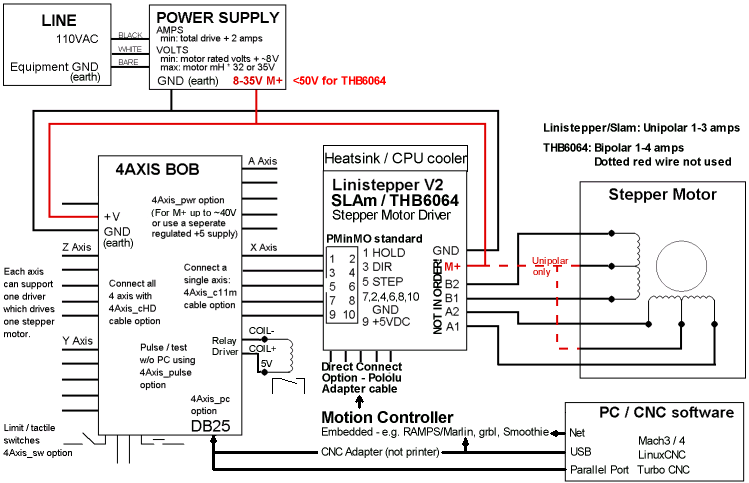
This block diagram of a stepper motor control system shows the basic components and links to more detailed information. Click on the highlighted areas.

See also:
Questions:
What are the issues involved with driving the THB6064 with 1 voltage (say 50V) and a controller board at 12V? by looking at the circuit diagram it appears that the logic ground and the motor ground on the THB6064 are common.
James Newton of MassMind replies: No problem. Just supply 50 volts for the motor power on the terminal block of the THB6064AH driver. Supply 5 volts (regulated) to the logic side connector (the 2x5 PMinMO header). The ground for both supplies must be common (as you note). There is no need for 12 volts, unless your motion controller (e.g. RAMPS) board needs it for some other function.+
Code:
Comments:
| file: /Techref/io/stepper/blockdiagram.htm, 5KB, , updated: 2019/12/19 17:42, local time: 2025/4/25 08:44,
3.139.86.128:LOG IN
|
| ©2025 These pages are served without commercial sponsorship. (No popup ads, etc...).Bandwidth abuse increases hosting cost forcing sponsorship or shutdown. This server aggressively defends against automated copying for any reason including offline viewing, duplication, etc... Please respect this requirement and DO NOT RIP THIS SITE. Questions? <A HREF="http://linistepper.com/Techref/io/stepper/blockdiagram.htm"> Stepper Motor Control Block Diagram</A> |
| Did you find what you needed? |